


Tüm Bloglar

Güneş Paneli Garanti Süresi ve Şartları Nelerdir
Atakale olarak sizlere güneş panelinin garanti şartlarını bir çok üreticinin hazırladığı dökümanlardan toplayarak aşağıda sunuyoruz..
Hemen hemen tüm üreticler garanti şartlarını tüketicinin süpriz olarak düşündüğü maddeler eklemektedir, en önemli garanti şartlarını aşağıda sizlere toplayıp bilgi olarka sunuyoruz.
HAzırlayan: Elkt. Müh. İsmail Hakkı Özdem
- Üreticinin yetkilendirmediği servisler tarafından ypaılan kurulum
- Ürün üzerine yapılan vida delik ve çerçeve deformasyonları (tüm panellerde kozmetik sorunlar omakta)
- Etiketin silinmesi ve çıkmış olması (15 sene dyanacak etiket neredeyse hiçbirinde yok)
- Yüksek ısılara maruz kalması 80º yi geçmesi / Yazın bu sıcaklıklara rahatlıkla ulaşabilmektedir
- Elektrik yönetmeliklerine aykırı kullanılması
-Mobil cihazlar, Karavanlar, Taşınabilir cihazlr üzerine kurulması titreşim ve sarsıntıya maruz kalması
- Faturasız ürünler
- Panelin montaj şekli kurallara uygun yapılmaması (panelin üstündeki izlerden anlaşıulmaktadır)
- Uyumsuz ürünlerle kulanılması (Özellikle Off-grid sistmemlerde)
- KAr , buz , birikintisinin üstünde yüksek gerilimler oluşturması
-
Sınırlı Garanti Kapsamının Kapsamı: Burada geçen garanti şartları, Güneş Paneli üreticilerinin genel olarak ürettiği panelleri kapsar . Üreticilerin özel şartlarının ortak maddelerini anlatır. (xxx = anma gücü) (bundan böyle "Ürün" olarak anılacaktır) ve üretici adına yetkili satış servisi olarak Atakale Elektronik veya bağlı şirketleri, bölümleri veya birimleri (bundan böyle "Atakale " olarak anılacaktır) tarafından satılır. ) ve orijinal son kullanıcı alıcısına kadar genişletilir ve Ürün ilk kurulduğu yerde kaldığında, tatmin edici bir halefiyet veya devir kanıtı (tüm bu kişiler bundan böyle "Müşteri" olarak anılacaktır).”).
Sınırlı Ürün İşçilik Garantisi. Atakale , Ürün'ün, Müşteri tarafından Ürün satın alındığı tarihten itibaren on beş (12) yıl boyunca, normal uygulama, kurulum, kullanım ve servis koşulları altında malzeme ve ürün işçiliği açısından kusursuz olacağını garanti eder. Ürün, Atakale’nin yegane ve mutlak takdirine bağlı olarak belirlendiği üzere, bu garantiye uymazsa, Atakale, aşağıdaki Kısım 4'te belirtilen Sınırlı Garanti Çözümlerinden birini uygulayacaktır. Bu on beş (12) yıllık Sınırlı Ürün İşçilik Garantisi, münhasıran aşağıdaki Bölüm 3 kapsamında kapsanacak olan belirli bir güç çıkışını garanti etmez.
Sınırlı Güç Çıkışı Garantisi. Atakale , Güç çıkışının, Ürünün Müşteri tarafından satın alındığı tarihten itibaren ilk yıl için ürün veri sayfasında belirtilen, belirlenen Maksimum Gücün (Pmax) %95'inden az olmayacağını ve güç çıkışındaki düşüşün Takip eden 24 yıl için yılda %0,6, böylece 25. yılın sonunda güç çıkışı Pmax'ın en az %80,6'sı olacaktır. Bu Sınırlı Güç Çıkışı Garantisi kapsamındaki güç çıkış değerleri, Atakale'nin Standart Test Koşulları (STC) kapsamında aşağıdaki şekilde ölçülen değerler olacaktır: (a) Işınım 1000 W/m2, (b) 25ºC Hücre Sıcaklığı ve (c) 1.5 Hava Kütlesi G.
Bir Güç Çıkışı garanti talebi alındığında, Atakale veya atanmış temsilcisi, Ürünün gerçek güç çıkışını belirlemek için STC kapsamında ölçümler gerçekleştirecektir. Atakale'in ölçümü, garanti anlaşması amacıyla tek belirleme olacaktır. Atakale, ±%3'lük bir ölçüm tolerans aralığını dikkate alarak, yukarıda belirtilen garantili çıkış seviyeleri altında güç çıkış seviyelerini ölçerse ve bu tür bir güç kaybı, Atakale 'in yegane ve mutlak takdirine bağlı olarak belirlendiği üzere, bir ürün kusurunun sonucuysa, Atakale aşağıda Bölüm 4'te belirtildiği gibi aşağıdaki Sınırlı Garanti Çözümlerinden birini kullanarak güç çıkışı eksikliğini tamamlayacaktır.
Sınırlı Garanti Çözümleri. Atakale, kendi takdirine bağlı olarak aşağıdaki çözüm yollarından birini alacaktır:
Atakale, Müşteriye orijinal Ürünün güç düşüm bedelini satın alma fiyatı üzerinden oransal olarak iade edebilir. Geri ödeme, Müşteriye satın alma tarihinden itibaren ay sayısına göre eşit olarak dağıtılabilir ve/veya gerçek güç çıkışı (Ürün STC kapsamında ölçülür) ile garanti edilen minimum çıktı arasındaki farka göre hesaplanabilir;
Atakale, eksik üretilen güç kadar ilave güneş paneli sağlayabilir;
Atakale, Ürünü onarabilir veya yeni veya yenilenmiş Ürünle değiştirebilir.
Sınırlı Çözüm Koşulları.
Sınırlı Garanti Çözümlerinden biri kullanıldığında, aşağıdaki koşullar geçerli olacaktır:
5.a Garanti çözümü, yalnızca garanti süresi sona ermeden önce alınan talepler için geçerli olacaktır.
5.b Orijinal garanti süresi yürürlükte kalır ve arızalı Ürünün onarımı, değiştirilmesi, eklenmesi veya eşit olarak iade edilmesi üzerine uzatılmaz ve yeni bir garanti süresi başlamaz.
5.c Orijinal Ürünün satın alma tarihi, Panasonic’in kusurlu Ürünü onarması, değiştirmesi, eklemesi veya iade etmesi durumunda garanti süresinin başlangıcını belirleyecektir.
5.d Çözüm seçenekleri birleştirilemez. Yalnızca Atakale’nin takdirine bağlı olarak yalnızca bir çözüm seçeneği kullanılacaktır.
5.e Garanti çözümü yalnızca Ürün için geçerlidir ve diğer sistem bileşenleri veya parçaları için geçerli değildir.
5.f Ürün, üçüncü şahıs finansmanına konu olduğunda, Ürün'ün hak sahibine geçerli herhangi bir geri ödeme ödenecektir.
5.g Ürünün çıkarılması, paketlenmesi, nakliyesi, yeniden kurulması ve ilgili maliyetler ve ücretler bu sınırlı garantilerin dışındadır.
5.h Panasonic ile değiştirilen Ürün, Atakale’nin malı olacaktır. Atakale, tamamen kendi tercihine bağlı olarak, boyut, renk, şekil, model numarası ve/veya güç seviyesi bakımından farklılık gösterebilecek başka bir tür yeni veya yenilenmiş Ürün teslim etme hakkını saklı tutar.
6 Sınırlı Garanti İstisnaları. Aşağıdaki şartlar oluşursa Yukarıdaki 2. ve 3. Bölümlerdeki garantiler geçersizdir ve aşağıdakiler şartlar geçerlidir
6.a Türkiye dışında satılan ve/veya kurulan Ürünler; ancak, Temsilciliğimizin bulunduğu herhangi biryerde ve bölgesinde satılan ve/veya kurulan herhangi bir Ürün, yukarıdaki Bölüm 2 ve 3'teki garantiler kapsamındadır.
6.b Garantinin sona ermesi, satın alma kanıtı olmaması veya kalifiye bir lisanslı güneş enerjisi veya elektrik yüklenicisi tarafından kurulum kanıtı olmaması.
6.c Değiştirilmiş, kaldırılmış veya okunaksız Ürün seri numarası/numaraları.
6.d Atakale dışında herhangi biri tarafından onarılan herhangi bir Ürün.
6.e Güç çıkışını etkilemeyen kozmetik varyasyonlar, lekeler veya çizikler.
6.f Deniz, eğlence aracı veya herhangi bir türde mobil kurulum. Çok eksenli takip sistemleri, mobil kurulumlar olarak kabul edilmez.
6.g Aynalarla kullanım, yoğun güneş ışığı ve güneş enerjisi sistemleriyle temas gibi ancak bunlarla sınırlı olmayan uygun olmayan uygulamalar.
6.h Genel Kurulum Kılavuzuna, Ulusal Elektrik Yasası gibi ulusal veya yerel yasalara veya Yargı Yetkisi Olan herhangi bir Otoriteye uyulmamasından kaynaklanan hasar.
i Kurum, kimyasal buharlar, asit yağmuru, deniz,okyanus gibi tuzlu su ile doğrudan temas, sel veya başka bir şekilde suya daldırma ve her türlü küf gibi çevre kirliliğinden kaynaklanan hasar veya korozyon.
6.j Normal aşınma ve yıpranma, eskime veya sürekli kullanımdan kaynaklanan ses, titreşim, pas, çizik veya renk bozulmasından kaynaklanan hasar.
6.k Yetersiz veya yanlış kullanım, değişiklik, kurulum, kablolama, taşıma, sökme, bakım, depolama, paketleme, nakliyeden kaynaklanan hasarlar.
6.l İddia edilen güç çıkışı düşüşü veya ürün işçiliği kusurunun makul bir şekilde keşfedildiği tarihten itibaren bir yıldan fazla bir süre içinde yapılan iddialar.
6.m Kötüye kullanım, ihmal, vandalizm, kaza, hayvanlar veya böcekler veya Ürüne basılması, aletler, golf topları, kayalar, dolu taşları veya diğer enkaz.
6.n Sistemle ilgili parçalar ve bileşenlerle uyumsuzluk veya kusurlardan kaynaklanan hasar.
6.o Depremler, tayfunlar, hortumlar, volkanik aktivite, tsunami, yıldırım, yoğun kar veya buz, yangın veya diğer öngörülemeyen durumlar gibi aşırı doğal koşullardan kaynaklanan hasarlar.
6.p Vidalar, cıvatalar, çiviler, aletler, sistem veya yapısal bileşenler, keskin kenarlar gibi nesnelerden kaynaklanan kesikler, sıyrıklar, çizikler, delikler, delinmeler veya aşınma ve yıpranma gibi ancak bunlarla sınırlı olmayan alt tabaka hasarı , sürekli sürtünme, ağaç dalları vb.
6.q Terör eylemleri, isyanlar, savaş, güç dalgalanmaları, elektrik kesintileri veya diğer insan yapımı felaketlerden kaynaklanan hasar.

Güneş Paneli Montajı Clamp Bağlantısı Nasıl Yapılır
MONTAJ YÖNTEMİ: CIVATALAMA
Bu montaj yöntemi Atakale Solar . tarafından onaylanmış ve VDE tarafından sertifikalandırılmıştır.
• Modüller, yalnızca arka çerçeve flanşlarındaki montaj deliklerinden destek yapılarına cıvatalanmalıdır.
• Her modül karşılıklı iki taraftan en az 4 noktadan emniyetli bir şekilde sabitlenmelidir.
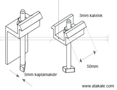
M8 X 1.25 - Derece 8.8 (5/16”-18 Derece B7) galvaniz veya A2-70 paslanmaz çelik cıvata ve somun kullanılmalıdır. Cıvata ve somunun akma dayanımı, 450 Mpa. Dan fazla olmalıdır
• M8 (5/16”-18) kalın dişli cıvatalar için, cıvata sınıfına bağlı olarak sıkma torkları sırasıyla 17~23 Nm (12,5~17,0 ft-lbs) olmalıdır.
• Ağır rüzgar yükü olan alanlarda ek montaj noktaları kullanılmalıdır. Sistem tasarımcısı ve kurulumcu şunlardan sorumludur:
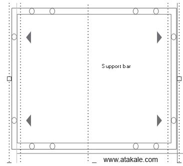
Dört Standart montaj deliği kullanarak kısa çerçeve tarafında cıvatalama. Montaj rayları, uzun çerçeve tarafına dik olarak uzanır. Modülün altına aşağıda gösterildiği gibi ek bir destek çubuğu yerleştirilmelidir.
Maksimum Yük: Kaldırma Yükü ≤ 2400 Pa Baskı Yükü ≤ 5400 Pa Uygun güneş paneli :tipleri: Poli, Mono Bifacial Asya, Avrupa, Amerika bölgeleri için uygun standartlar
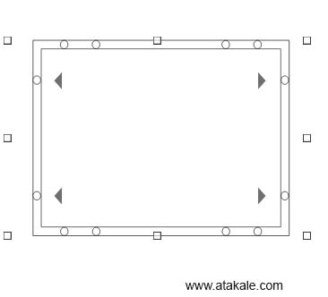
En içteki dört montaj deliğini kullanarak uzun çerçeve tarafında cıvatalama. Montaj rayları, uzun çerçeve tarafına paralel uzanır.
Maksimum Yük:Kaldırma Yükü ≤ 2400 Pa Baskı Yükü ≤ 5400 Pa Uygun güneş paneli :tipleri: Poli, Mono Bifacial Asya, Avrupa, Amerika bölgeleri için uygun standartlar
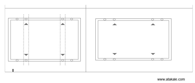
En içteki dört montaj deliğini kullanarak uzun çerçeve tarafında cıvatalama. Montaj rayları, uzun çerçeve tarafına dik olarak uzanır.
Maksimum Load:Kaldırma Yükü ≤ 2400 Pa Baskı Yükü ≤ 5400 Pa
Uygun güneş paneli :tipleri: Poli, Mono Bifacial Asya, Avrupa, Amerika bölgeleri için uygun standartlar.
En içteki dört montaj deliğini kullanarak uzun çerçeve tarafında cıvatalama. Montaj rayları, uzun çerçeve tarafına paralel uzanır.
Maksimum Load:Kaldırma Yükü ≤ 2400 Pa Baskı Yükü ≤ 5400 Pa Uygun güneş paneli :tipleri: Poli, Mono Bifacial Asya, Avrupa, Amerika bölgeleri için uygun standartlar)
Dört orta montaj deliği kullanarak uzun çerçeve tarafında cıvatalama. Montaj rayları, uzun çerçeve tarafına dik olarak uzanır.Maksimum Load:
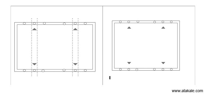
En içteki dört montaj deliğini kullanarak uzun çerçeve tarafında cıvatalama. Montaj rayları, uzun çerçeve tarafına dik olarak uzanır. Maksimum Load:
Kaldırma Yükü ≤ 2400 Pa Baskı Yükü ≤ 5400 Pa Uygun güneş paneli :tipleri: Poli, Mono Bifacial Asya, Avrupa, Amerika bölgeleri için uygun standartlar
Dört orta montaj deliği kullanarak uzun çerçeve tarafında cıvatalama. Montaj rayları, uzun çerçeve tarafına dik olarak uzanır
Maksimum Yük:Kaldırma Yükü ≤ 2400 Pa Baskı Yükü ≤ 5400 Pa Uygun güneş paneli :tipleri: Poli, Mono Bifacial Asya, Avrupa, Amerika bölgeleri için uygun standartlar
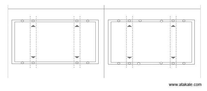
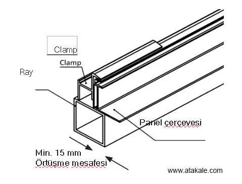
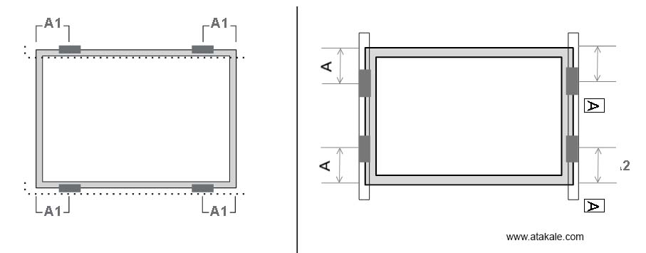
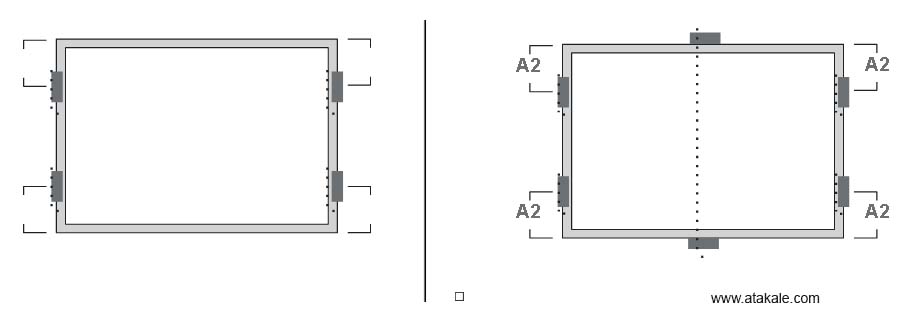
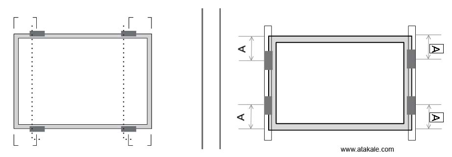
hesaplamalarından ve destek yapısının uygun tasarımından sorumludur. • Kelepçe malzemesi eloksallı alüminyum alaşımlı veya paslanmaz çelik olmalıdır. • Montajın güvenilirliği için kelepçe konumları çok önemlidir. Kelepçe merkez çizgileri, configürasyona ve yüke bağlı olarak yalnızca tablo A'da belirtilen aralıklar içinde konumlandırılmalıdır. · Montaj raylarının çerçeveye paralel uzandığı konfigürasyonlarda, modül çerçevesinin alt flanşının rayla 15 mm (0,59 inç) veya daha fazla örtüşmesini sağlamak için önlemler alınmalıdı.
Uzun kenarda dört clamp kullanın. Montaj rayları uzun yan çerçeveye dik olarak uzanır. A1 mesafe = (340 – 550) mm Maksimum Yük Çekme Yükü ≤ 2400 Pa İtme yükü load ≤ 2400 Pa . Uzun kenarda iki kıskaç ve kısa kenarda iki kıskaç kullanın. Montaj rayları uzun yan çerçeveye dik olarak uzanır.
A1 mesafe = (340 – 550) mm Maksimum Yük Çekme Yükü ≤ 2400 Pa İtme yükü load ≤ 2400 Pa A2 mesafesi 200-250mm
Kısa kenarda dört clamp ve uzun kenarda iki kıskaç kullanın. Modülün merkezinin altına ek bir destek çubuğu yerleştirilmelidir.
A2 mesafe = (200 – 250) mm Çekme Yükü ≤ 2400 Pa İtme yükü ≤ 5400 Pa
Kısa kenarda dört clamp kullanın. Montaj rayları uzun yan çerçeveye dik olarak uzanır. A mesafe = (200 - 250 mm) Maksimum Yük:
Çekme Yükü ≤ 1400 Pa İtme yükü ≤ 1400 Pa A mesafesş = ( 0 - 200 mm) Maksimum Yük: Çekme Yükü ≤ 1200 Paİtme Yükü ≤ 1200 Pa
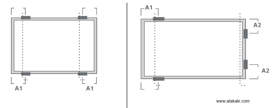
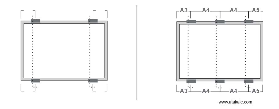
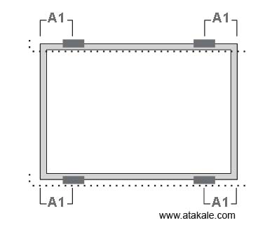
Uzun kenarda dört kıskaç kullanın. Montaj rayları uzun yan çerçeveye dik olarak uzanır.
A1 mesafe = (340 – 550) mm Maksimum Yük: Çekme Yükü ≤ 2400 Pa İtme Yükü ≤ 2400 Pa
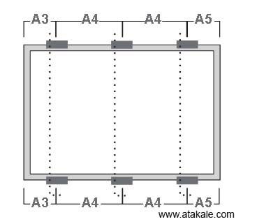
Uzun kenarda altı kıskaç kullanın.Montaj rayları uzun yan çerçeveye dik olarak uzanır.
A3 mesafe = (250– 350) mm A5 mesafe = (250– 350) mm Maksimum Yük Uplift load ≤ 2400 Pa İtme yükü ≤ 5400 Pa Uyarı: Bu yöntem daha iyi güvenilirlik için önerilir.
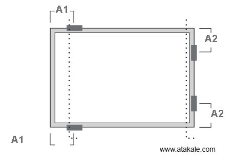
Uzun kenarda dört kıskaç kullanın. Montaj rayları uzun yan çerçeveye dik olarak uzanır. Kısa kenarda dört kıskaç kullanın. Montaj rayları uzun yan çerçeveye paralel uzanır.
A1 mesafe = (0 – 239) mm Maksimum Yük: Çekme Yükü ≤ 2000 Pa İtme Yükü ≤ 2000 Pa
A1 mesafe = (240 – 330) mm Maksimum Yük: Çekme Yükü ≤ 3600 Pa İtme Yükü ≤ 5400 Pa
A1 mesafe = (331 – 550) mm Maksimum Yük: Çekme Yükü ≤ 2400 Pa İtme Yükü ≤ 2400 Pa
Kısa kenarda dört kıskaç kullanın. Montaj rayları uzun yan çerçeveye paralel uzanır.
A2 mesafe = (200 – 250) mm Maksimum Yük Çekme ≤ 2000 Pa İtme ≤ 2000 Pa
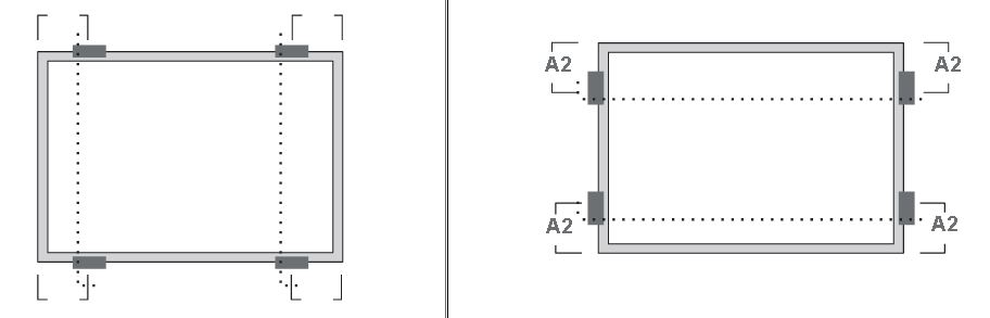
Kısa kenarda dört kıskaç kullanın. A2 mesafe = (200 – 250) mm Maksimum Yük: Çekme Yükü ≤ 2200 Pa İtme Yükü ≤ 2200 Pa
A2 mesafe = (0 – 200) mm Maksimum Yük: Çekme Yükü ≤ 2000 Pa İtme Yükü ≤ 2000 Pa
Kısa kenarda dört kıskaç ve uzun kenarda iki kıskaç kullanın. Modülün merkezinin altına ek bir destek çubuğu yerleştirilmelidir.
A2 mesafe = (200 – 250) mm Maksimum Yük Uplift load ≤ 2400 Pa Downforce load ≤ 5400 Pa
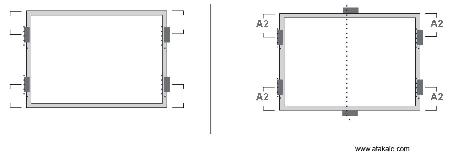
Uzun kenarda dört kıskaç kullanın. Montaj rayları uzun yan çerçeveye paralel uzanır. A1 Mesafe = (240 – 330) mm Maksimum Yük: Çekme Yükü ≤ 2400 Pa İtme yükü ≤ 4000 Pa
Uzun kenarda dört kıskaç kullanın. Montaj rayları uzun yan çerçeveye dik olarak uzanır.
A1 mesafe = (340 – 550) mm Maksimum Yük: Çekme Yükü ≤ 2400 Pa İtme Yükü ≤ 2400 Pa
A1 mesafe = (410 – 490) mm Maksimum Yük: Çekme Yükü ≤ 3600 Paİtme Yükü ≤ 5400 Pa

Güneş Paneli Kullanma Klavuzu ve Montajı
 .0 GENEL BİLGİLERİ
Bu genel kılavuz, Atakale güneş modüllerinin kurulumu, bakımı ve kullanımıyla ilgili önemli güvenlik bilgileri Standart. Profesyonel kurulumcu bu yönergeleri dikkatlice okumalı ve bu yönergeleri kesinlikle izlemelidir. Bu talimatlara uyulmaması ölüm, yaralanma veya maddi hasara neden olabilir. PV modüllerinin kurulumu ve kullanımı profesyonel beceriler gerektirir ve yalnızca kalifiye profesyoneller tarafından gerçekleştirilmelidir. Montajcılar, son kullanıcılara (tüketicilere) yukarıda belirtilen bilgileri uygun şekilde bildirmelidir. Bu kılavuzda kullanılan "modül" veya "PV modülü" kelimesi, bir veya daha fazla Atakale serisi güneş modülünü ifade eder.
Bu klavuz, monokristal, polikristal, halfcut , cam cama güneş panellerinin kurulum ve kullanımıyla ilgili bilig verir Atakale panelleri için, Standart lokasyon Avrupa , Asya Afrika ve Amerikadır için içindir Japonya bölgesi içinde geçerlidir. Montaj yöntemlerini öğrenmek için lütfen ayrı Ek E: için Montaj Yöntemi Bağlama bölümüne bakın.) Lütfen bu kılavuzu ileride başvurmak üzere saklayın. www.atakale.com'a bakmanızı tavsiye ederiz. En güncel sürüm için düzenli olarak sitmeizi kontrol edebilirsiniz
1.1 KURULUM KLAVUZU SORUMLULUK REDDİ VE UYARILAR
Bu kılavuzda yer alan bilgiler önceden haber verilmeksizin atakale. tarafından değiştirilebilir. Atakale açıkça veya zımnen hiçbir şekilde garanti vermez,burada yer alan bilgilerle ilgili olarak sadece normal şartlardaki kullanımlarla ilgili bilgi içerir. Kurulumdan önce mutlaka servisi arayınız.Yetkili kşiler haricinde yapılan montaj ve kurulumlarla ilgili bu klavuz yeterli değildir.Kesinlikle tehlikeli ve ciddi tehlike içerir. Bu belgenin farklı dillerdeki versiyonları arasında herhangi bir tutarsızlık olması durumunda, İngilizce versiyonu geçerli olacaktır. Bu listeler düzenli olarak güncellendiğinden lütfen http://www.atakale.com adresindeki web sitemizde yayınlanan ürün listelerimize ve belgelerimize bakın
1.2 SORUMLULUĞUN SINIRLANDIRILMASI
Atakale Solar ,yazılanlarla sınırlı olmamak üzere,burada vermi olduğu teknik bilgileri yetkili bir seris haricinde uygulayan kişilerin oluşturaağı herhangi bir zarardan sorumlu tutulamaz.
– PV modüllerinin taşınması, sistem kurulumu veya bu kılavuzda belirtilen talimatlara uyulmaması ile bağlantılı olarak bedensel zarar,yaralanma veya mal hasarı sonuçları doğurabilir.
UYARI! Panelleri ve aksesuarlarını takmaya, kablolamaya, çalıştırmaya bakımını yapmaya çalışmadan önce, tüm talimatlar okunmalı ve anlaşılmalıdır. PV modül konektörleri, güneş ışığına veya diğer ışık kaynaklarına maruz kaldığında doğru akımı (DC) geçirir. Modülün terminaller gibi elektriksel olarak aktif parçalarıyla temas, modülün ve diğer elektrikli ekipmanın bağlı olup olmadığına bakılmaksızın yaralanma veya ölümle sonuçlanabilir.GENEL GÜVENLİK · Tüm modüller, en son Ulusal Elektrik Yasası ve Avrupa gibi geçerli elektrik yasalarına veya diğer ulusal veya uluslararası geçerli elektrik yasalarına uygun olarak lisanslı elektrikçiler tarafından kurulmalıdır. Montaj sırasında 30 V DC veya üzeri ile doğrudan teması önlemek ve elleri korumak için koruyucu giysiler eldiven giyilmelidir.
 Kurulumdan önce elekrik çarpmalarına kazara maruz kalmayı önlemek için tüm metal takıları çıkarın.
 Modülleri hafif yağmurda, sabah çiyinde takarken, konektöre su girmesini önlemek için uygun önlemleri alın.
 Modüllerin kurulum sahası veya depolama alanı yakınında çocuklara veya yetkisiz kişilere izin vermeyin.
-
Beklenen En Düşük Ortam Sıcaklığı(°C/°F)
Gerilim akımın artış miktarı Düzeltme Faktörü
24 - 20 / 76 to 68
1.02
19 - 15 / 67 to 59
1.04
14- 10 / 58 to 50
1.06
9 - 5 / 49 to 41
1.08
-
-6 arası -10 / 22 t-14
1.14
-11 arası -15 / 13 to 5
1.16
-16 arası -20 / 4 to -4
1.18
-21 arası -25 / -5 to -13
1.20
-26 arası -30 / -14 to -22
1.21
-31 arası -35 / -23 to -31
1.23
-36 arası -40 / -32 to -40
1.25
 5.0 GÜNEŞ PANELİ MONTAJI
 Panelleri alev ve patlama tehlikesi olan yerlere yakın kurmayın Panelleri suya daldırmayın ve modülleri sürekli olarak suya (tatlı veya tuzlu) maruz bırakmayın
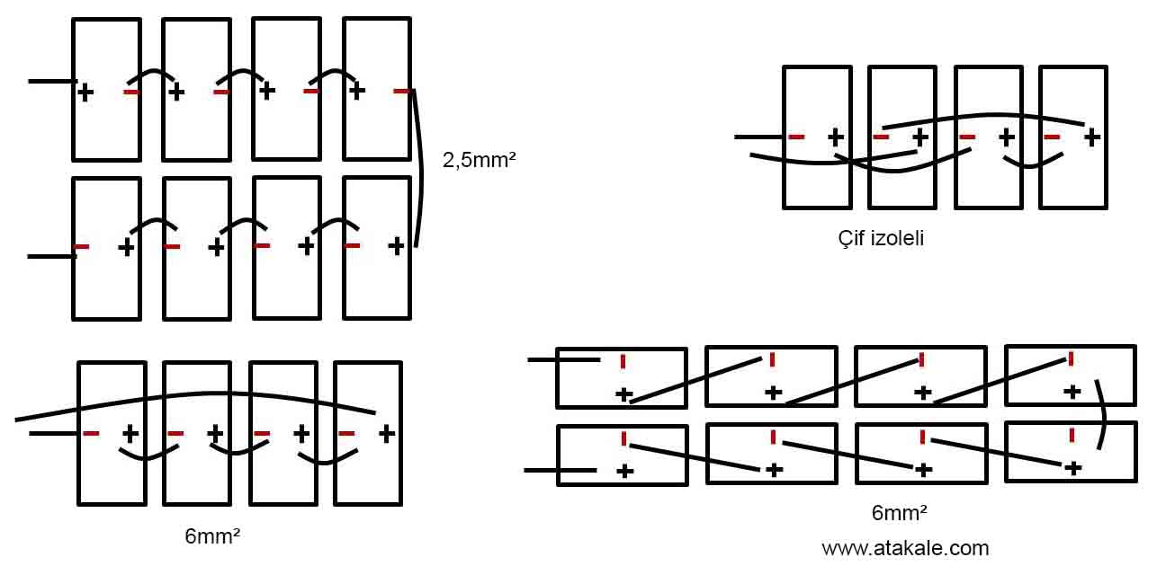
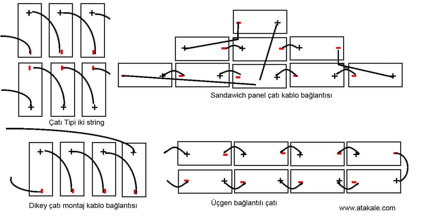
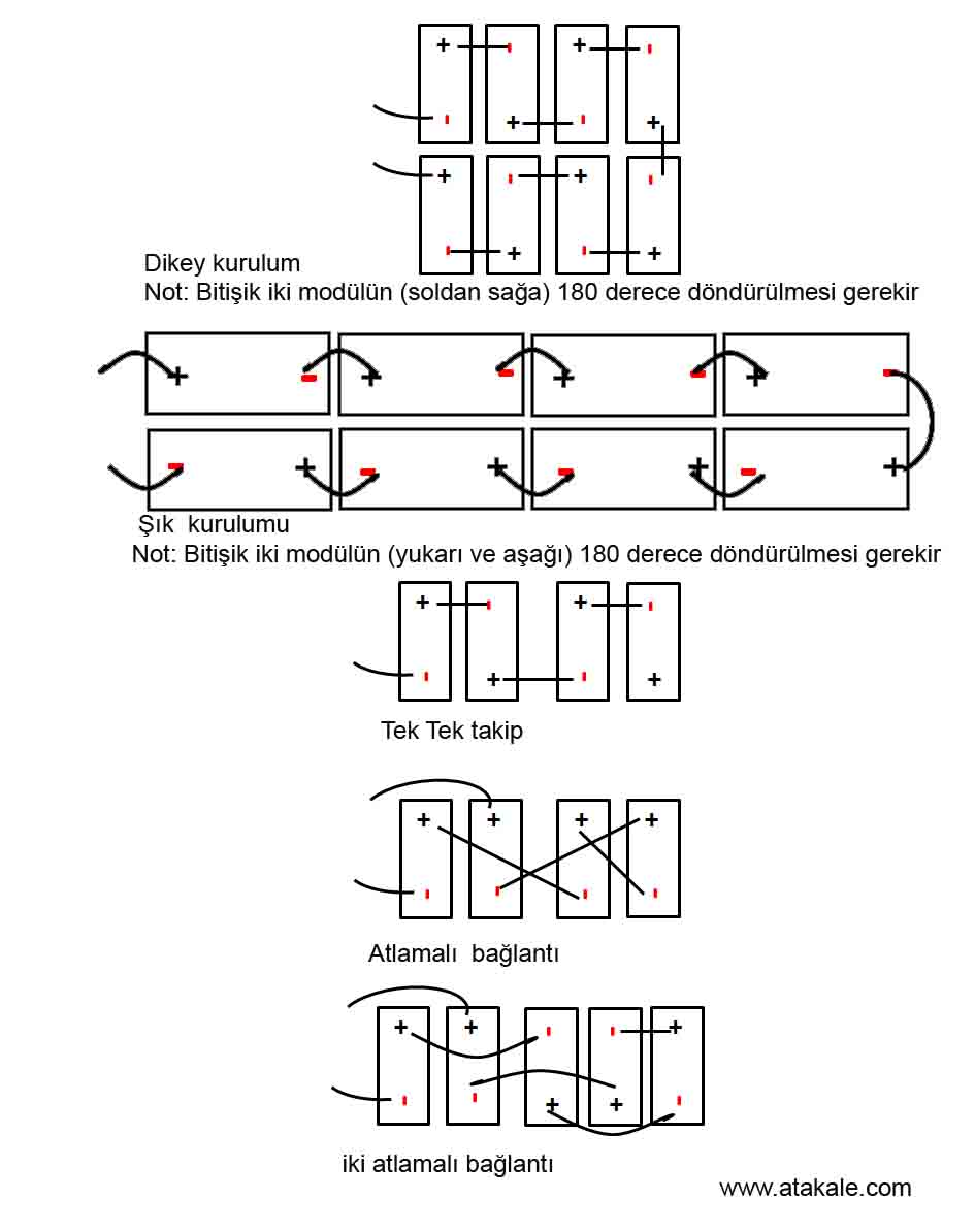
Sistem kablo şemasını karşılamak için iki bitişik modül çerçevesi arasındaki maksimum mesafe, montaj kelepçeleri olan taraf için 50 mm (1,96 inç) ve montaj kelepçeleri olmayan taraf için 25 mm (0,98 inç) içinde olmalıdır.
MC4 KONNEKTÖRLERİNİN DOĞRU BAĞLANTISI
◦ Tüm bağlantıların güvenli ve doğru şekilde eşleştirildiğinden emin olun. PV konektörü dışarıdan gelen çekemye maruz bırakılmamalıdır. Konektörler sadece devreyi bağlamak için kullanılmalıdır. Devreyi açıp kapatmak için asla kullanılmamalıdırlar.
◦ Konektörler, eşleştirilmediği zaman su geçirmez değildir. Modülleri takarken, konektörler mümkün olan en kısa sürede birbirine bağlanmalı veya konektöre nem ve toz girmesini önlemek için uygun önlemler alınmalıdır.
◦ Konektörleri yağlayıcılar veya izin verilmeyen herhangi bir kimyasal madde kullanarak temizlemeyin veya ön koşullandırma yapmayın.
UYGUN MALZEME KULLANIMI
◦ Yalnızca yerel yangın, bina ve elektrik yönetme liklerine uygun özel güneş enerjisi kablosu ve uygun konektörler kullanın (kablolar güneş ışığına dayanıklı bir kanalda veya maruz kalması durumunda güneş ışığına dayanıklı olmalıdır).
◦ Tesisatçılar, yalnızca USE-2 veya PV teli olarak listelenmiş ve etiketlenmiş tek iletkenli kablo kullanabilirler. Uluslararası 90°C suya dayanıklı olarak sınıflandırılmıştır ve tek iletkenli kablo, 2.5-16 mm² (5-14 AWG ), diğer alanlarda 90°C suya dayanıklı olarak sınıflandırılmıştır (yani TUV 2PfG1169 veya EN50618 onaylı), uygun izolasyona sahip, mümkün olan maksimum sistem açık devre voltajına dayanmalıdır.
◦ Sadece bakır iletken malzeme kullanıl malıdır. Voltaj düşüşünü en aza indirmek için uygun bir iletken ölçer seçin ve iletken akımının yerel düzenlemelere (yani NEC 690.8(D)) uygun olduğundan emin olun.
KABLO VE KONNEKTÖRLERİN KORUMASI
◦ UV ışınlarına dayanıklı kablo bağları kullanarak kabloları montaj sistemine sabitleyin. Uygun önlemleri alarak (örneğin, bunları EMT kanalı gibi metalik bir kanal içine yerleştirerek) açıkta kalan kabloları hasardan koruyun. Doğrudan güneş ışığına maruz kalmaktan kaçının. Bağlantı kutusu kablolarını raf sistemine sabitlerken minimum 60 mm (2,36 inç) bükülme yarıçapı gereklidir.
Konektörleri suyun kolayca birikebileceği yerlere yerleştirmeyin. Konnektörleri su birikecek yerlere koymayınız.
TOPRAKLAMA
• Standart opraklama yönetmen liğpi için, açıkta kalan iletken parçalara sahip bir modülün, yalnızca aşağıda verilen talimat lara ve Ulusallararası Elektrik Yönetmenliklere göre kurulması gerek lidir. Atakale . modülleri ile kullanılan herhangi bir topraklama aracı UL 467 ve UL 2703 standartlarına göre NRTL sertifikalı olmalıdır. Resmi onay süreci için lütfen teknik servis ekibimize danışınız.
• Diğer alanlardaki topraklama yönetme likleri için modüller Güvenlik Sınıfı II sertifikasına sahip olsa da, topraklanmalarını Stanartlara uygun yapılması gerekir
• Topraklama bağlantıları, bir kalifiye elektrikçiye yaptırmanız gerekir.
• Modül çerçevelerini yeterli topraklama kabloları kullanarak birbirine bağlayın: 4-14 mm² (AWG 6-12) bakır tel kullanılmasını öneririz. Bu amaç için sağlanan delikler, bir topraklama sembolü ile tanımlanır (IEC 61730-1). Tüm iletken bağlantı noktaları sıkıca sabitlenmelidir.
• Kolaylık sağlamak için fazladan toprakla ma deliği açmayın, bu modül garantisini geçersiz kılacaktır.
• Aksi belirtilmedikçe tüm cıvatalar, somunlar, düz rondelalar, kilit rondelaları ve diğer ilgili donanımlar paslanmaz çelikten yapılmalıdır.
• Atakale Solar topraklama donanımı sağlamaz. Topraklama ürünleri montajcı tarafından projeye uygun tedarik edilir
• Atakale Solar Inc. Standart modülleri için aşağıda açıklandığı gibi bir topraklama yöntemi önerilir. Alternatif topraklama yöntemleri için lütfen bu kurulum kılavuzunun Ek B'ye (Alternatif Topraklama Yöntemleri) bakın. Bazı durumlarda Standart topraklama yöntemlerini kullanmak mümkün olmayabilir.

· Bir M5 (3/16") SS başlık cıvatası, bir M5 (3/16") SS düz pul, bir M5 (3/16") SS çanak pul ve bir M5 (3/16") içeren bir topraklama kiti SS somunu (dişli), çerçeve üzerinde var olan bir topraklama deliğine bakır topraklama teli takmak için kullanılır (aşağıdaki resme bakın).
· Teli düz rondela ile ters rondela arasına yerleştirin. Galvanik korozyonu önlemek için fincan pulunun içbükey tarafı yukarı gelecek şekilde çerçeve ile tel arasına yerleştirildiğinden emin olun. SS dişli somunu kullanarak cıvatayı iyice sıkın. Bunu yapmak için bir anahtar kullanılabilir. Sıkma torku 3-7 Nm'dir (2,2-5,2 ft-lbs)

Half Cut Güneş Paneli Avantajları ve Yenilikleri
Yarım Kesim / Half Cut Güneş Paneli Özellikleri Avantajları
Standart Güneş Panellerinde kullanılan hücrelerin lazer ile ikiye bölünerek kullanılır. Hücre sayısı normal diğer panellere göre iki kattır. Avantajı, iç dirençlerinin düşük olması dolayısıyla aynı alanda %7 daha fazla verim sağlar. Ayrıca multibus teknolojisi half cutlarda kullanıldığından verim %3 daha fazladır. Çok az ışık ortamında bile, gelen güneş enerjisini elektrik enerjisine çevirilir, ve diğer mono perc lere göre %10 civarı daha yüksek düşük ışık şiddetlerinde verim elde edilir. Kullanılan hücreler diğer panellerdeki hücrelerle aynıdır.Diğer hücreler çok büyük olduğundan titreşim ve panelin esneme lerinde mikro çatlaklar oluşturduğu halde Half Cut panellerde bu çatlaklar daha az ve çok daha uzun sürede oluşur. Buda panelin 30 senelik ekonomik ömrü boyunca daha yüksek verimle elektrik üretmesini sağlar. Buda yatırım maiyetlerini düşürür.
Modül/Panel verimini bu yöntemle %21,5 seviyesine çıkartabiliriz, Şimdiden tüm üreticiler bu teknolojiyi üretim bantlarına uygulamak için çalışmaya başladılar bile. Half Cut ve Multi Bus Bar (9/12 bus bar) teknolojisi birlikte uyguladığında panel verimi %23,5 a kadar çıkabilir.
Panel iki ayrı bölgeye bölündüğünden gölgenin çok olduğu yerlerde büyük avantaj sağlar. Örnek ağaçların arasında montajını yaptığınız güneş panelinin üzeirne gölge düştüğünde sadece panelin %50 si bundan etkilenir, diğer kısım üretime devam eder.
Daha az alanda daha yüksek güç elde edilmesi saysesinde konstrüksiyon maliyetleride %10 azalacaktır.
Güneş enerjiyle üreitlen fotonaların toplandığı bus barların adedi fazla olduğundan, iç direnç sebebiyle oluşan ısı Half Cut da daha azdır
Bu konuyla ilgili blog yazımızı okuyabilirsiniz
Half Cut Panellerin Sakıncaları Dezavantajları
Fiyatlar yüksektir, ürettiğiniz enerjinin amortisman süresi daha uzundur. Daha fazla hücre kullanıldığından hata ve arıza riski konvansiyonel panellere oranla yüksektir. Lexron, İzmirde ACS Enerji Firmasının 2017 yılından beri üretim yaptığı yerli markasıdır.
Gölgelemenin olmadığı açık uygulamalarda fiyatlarının pahalı olması sebebiyle avantajı değillerdir. Ek yerleri fazla olduğundan ,Kısa devre durumlarında daha güvensizdirler. Lazerle kesilen bölgelerin performansı düşüktür. Yeni bir teknoloji olduğundan 30 sene ömür biçmek teorik bir yaklaşımdır, çıkacak pratik hata ve problemlerin henüz iyi bilinenmemesi, bir çok yatırımcıyı kuşkulandırmaktadır. 30senedir tecrübe edilmiş ve enerji üretim performansları %100 kesin olan konvansiyonel panellerin yerine , küçük bir kaç avantajı dolayısyla tecrübe edilmemeiş ömür garantili half cut tercih edilmesi ciddi bir risktir.
Eski teknolojide kullanılan aynı hücrelerin sadece ikiye bölünerek kullanılması üstün teknolojik bir yenilik değildir.