 .0 GENEL BİLGİLERİ
Bu genel kılavuz, Atakale güneş modüllerinin kurulumu, bakımı ve kullanımıyla ilgili önemli güvenlik bilgileri Standart. Profesyonel kurulumcu bu yönergeleri dikkatlice okumalı ve bu yönergeleri kesinlikle izlemelidir. Bu talimatlara uyulmaması ölüm, yaralanma veya maddi hasara neden olabilir. PV modüllerinin kurulumu ve kullanımı profesyonel beceriler gerektirir ve yalnızca kalifiye profesyoneller tarafından gerçekleştirilmelidir. Montajcılar, son kullanıcılara (tüketicilere) yukarıda belirtilen bilgileri uygun şekilde bildirmelidir. Bu kılavuzda kullanılan "modül" veya "PV modülü" kelimesi, bir veya daha fazla Atakale serisi güneş modülünü ifade eder.
Bu klavuz, monokristal, polikristal, halfcut , cam cama güneş panellerinin kurulum ve kullanımıyla ilgili bilig verir Atakale panelleri için, Standart lokasyon Avrupa , Asya Afrika ve Amerikadır için içindir Japonya bölgesi içinde geçerlidir. Montaj yöntemlerini öğrenmek için lütfen ayrı Ek E: için Montaj Yöntemi Bağlama bölümüne bakın.) Lütfen bu kılavuzu ileride başvurmak üzere saklayın. www.atakale.com'a bakmanızı tavsiye ederiz. En güncel sürüm için düzenli olarak sitmeizi kontrol edebilirsiniz
1.1 KURULUM KLAVUZU SORUMLULUK REDDİ VE UYARILAR
Bu kılavuzda yer alan bilgiler önceden haber
verilmeksizin atakale. tarafından değiştirilebilir.
Atakale açıkça veya zımnen hiçbir şekilde garanti
vermez,burada yer alan bilgilerle ilgili olarak sadece
normal şartlardaki kullanımlarla ilgili bilgi içerir.
Kurulumdan önce mutlaka servisi arayınız.Yetkili
kşiler haricinde yapılan montaj ve kurulumlarla ilgili
bu klavuz yeterli değildir.Kesinlikle tehlikeli ve ciddi
tehlike içerir.
Bu belgenin farklı dillerdeki versiyonları arasında
herhangi bir tutarsızlık olması durumunda, İngilizce
versiyonu geçerli olacaktır. Bu listeler düzenli olarak
güncellendiğinden lütfen http://www.atakale.com
adresindeki web sitemizde yayınlanan ürün
listelerimize ve belgelerimize bakın
1.2 SORUMLULUĞUN SINIRLANDIRILMASI
Atakale Solar ,yazılanlarla sınırlı olmamak üzere,burada vermi olduğu teknik bilgileri yetkili bir seris haricinde uygulayan kişilerin oluşturaağı herhangi bir zarardan sorumlu tutulamaz.
– PV modüllerinin taşınması, sistem kurulumu veya bu kılavuzda belirtilen talimatlara uyulmaması ile bağlantılı olarak bedensel zarar,yaralanma veya mal hasarı sonuçları doğurabilir.
2.0 GÜVENLİK ÖNLEMLERİ
UYARI! Panelleri ve aksesuarlarını takmaya, kablolamaya, çalıştırmaya bakımını yapmaya çalışmadan önce, tüm talimatlar okunmalı ve anlaşılmalıdır. PV modül konektörleri, güneş ışığına veya diğer ışık kaynaklarına maruz kaldığında doğru akımı (DC) geçirir. Modülün terminaller gibi elektriksel olarak aktif parçalarıyla temas, modülün ve diğer elektrikli ekipmanın bağlı olup olmadığına bakılmaksızın yaralanma veya ölümle sonuçlanabilir.
UYARI:
Devam etmeden önce tüm talimatlar
okunmalı ve anlaşılmalıdır.
panellerin kurulumu, kablolaması, çalıştırılması
ve/veya bakımı. Panel ara bağlantıları, panel güneş
ışığına veya diğer ışık kaynaklarına maruz kaldığında
doğru akım (DC) iletir. Panelin çıkış terminalleri gibi
canlı bölümleriyle temas, panel bağlı olsun veya
olmasın yaralanma veya ölüme neden olabilir.
GENEL GÜVENLİK · Tüm modüller, en son Ulusal Elektrik Yasası ve Avrupa gibi geçerli elektrik yasalarına veya diğer ulusal veya uluslararası geçerli elektrik yasalarına uygun olarak lisanslı elektrikçiler tarafından kurulmalıdır.

Montaj sırasında 30 V DC veya üzeri ile doğrudan teması önlemek ve elleri korumak için koruyucu giysiler eldiven giyilmelidir.

Kurulumdan önce elekrik çarpmalarına kazara maruz kalmayı önlemek için tüm metal takıları çıkarın.

Modülleri hafif yağmurda, sabah çiyinde takarken, konektöre su girmesini önlemek için uygun önlemleri alın.

Modüllerin kurulum sahası veya depolama alanı yakınında çocuklara veya yetkisiz kişilere izin vermeyin.
• Modülleri kuvvetli rüzgarda kurmayın.
• Elektrik çarpması riskini azaltmak için elektrik yalıtımlı aletler kullanın
• Bağlantı kesiciler ve Aşırı Akım Koruma Cihazı (OCPD) açılamıyorsa veya invertör kapatılamıyorsa, PV dizisindeki modüllerin önlerini opak bir malzeme ile kaplayarak, bir cihaz devreye alırken veya üzerinde çalışırken elektrik üretimini durdurun. modül veya kablolamada enerji varken çalışmayın..
• Hasarlı modülleri kullanmayın veya kurmayın. Atakale servisini arayarak panelle ilgili bilgi alın
• Modül yüzeyleri veya çerçevelerle temas, ön camın kırılması veya arka tabakanın yırtılması durumunda elektrik çarpmasına neden olabilir..
• PV modülü, servis edilebilir herhangi bir parça içermez. Modülün herhangi bir parçasını onarmaya çalışmayın.
• Bağlantı kutusu kapağını her zaman kapalı tutun..
• Bir modülü sökmeyin veya herhangi bir modül parçasını çıkarmayın.
• Güneş ışığını yapay olarak bir modül üzerinde yoğunlaştırmayın.
• Modüllerden akım veya harici bir kaynak mevcutken modülleri bağlamayın veya bağlantısını kesmeyin.
3.0 MEKANİK / ELEKTRİK ÖZELLİKLERİ
Modül elektrik değerleri, AM1.5 spektrumu ve 25°C hücre sıcaklığı ile 1000 W/m2 ışınımlık Standart Test Koşulları (STC) altında ölçülür. Atakale Solar kristal silikon PV modüllerinin ayrıntılı elektriksel ve mekanik özellikleri Ek C'de (Mekanik ve Elektrik Derecelendirmeleri) bulunabilir.
www.atakale.com. STC'deki ana elektriksel özellikler de her modül etiketinde belirtilmiştir. Maksimum sistem voltajı için lütfen veri sayfasına veya ürün isim plakasına bakın.
Belirli koşullar altında, bir modül, Standart Test Durumunun nominal gücünden daha fazla akım veya voltaj üretebilir. Sonuç olarak, STC altındaki modül kısa devre akımı 1,25 ile çarpılmalı ve bileşen derecelendirmeleri ve kapasiteleri belirlenirken açık devre voltajına bir düzeltme faktörü uygulanmalıdır (aşağıdaki Tablo 1'e bakınız).
Yerel düzenlemelerinize bağlı olarak, ek bir
Kısa devre akımı için 1,25 çarpanı (toplam 1,56 çarpanı vererek) iletkenleri ve sigortaları boyutlandırırken uygulanabilir.
SICAKLIK DÜŞTÜKÇE GÜNEŞ PANELİNİN ÜRETTİĞİ AKIM GERİLİM VE GÜÇ ARTAR. -25ºc de güç %25 artmaktadır. Tabloda güneş panelinin sıcaklıklarda ürettiği gerilim artış oranları verilmiştir
-
Beklenen
En Düşük Ortam Sıcaklığı(°C/°F)
|
|
Gerilim
akımın artış miktarı Düzeltme Faktörü
|
24
-
20
/
76
to
68
|
|
1.02
|
19
-
15
/
67
to
59
|
|
1.04
|
14-
10
/
58
to
50
|
|
1.06
|
9
-
5
/
49
to
41
|
|
1.08
|
-
-6
arası
-10
/
22
t-14
|
|
1.14
|
-11
arası
-15
/
13
to
5
|
|
1.16
|
-16
arası
-20
/
4
to
-4
|
|
1.18
|
-21
arası
-25
/
-5
to
-13
|
|
1.20
|
-26
arası
-30
/
-14
to
-22
|
|
1.21
|
-31
arası
-35
/
-23
to
-31
|
|
1.23
|
-36
arası
-40
/
-32
to
-40
|
|
1.25
|
Alternatif olarak, açık devre gerilimi için daha doğru bir düzeltme faktörü aşağıdaki formül kullanılarak hesaplanabilir:
CVOC = 1-αVoc ˣ (25 - T)
T sistem kurulum sahasında beklenen en düşük ortam sıcaklığıdır
αVoc (%/ºC), seçilen modülün voltaj sıcaklık katsayısıdır (ilgili veri sayfasına bakın)
Elektriksel hesaplamalar ve tasarım, yetkin mühendis veya danışman tarafından yapılmalıdır.
4.0 Paltlerin Amblajın Açılması ve Depolama
ÖNLEMLER
• Atakale Modülleri, doğrudan güneş ışığı ve nemden kaçınmak için kuru ve havalandırılmış bir ortamda saklanmalıdır. Modüller kontrolsüz bir ortamda depolanıyorsa, depolama süresi 3 aydan az olmalı ve konektörlerin neme maruz kalmaması için ekstra önlemler alınmalıdır.
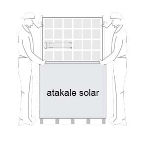
• Palet üzerinde gösterilen adımları izleyerek modül paletlerini dikkatli bir şekilde ambalajından çıkarın..
• Modüller her zaman iki kişi tarafından ambalajından çıkarılmalı ve kurulmalıdır. Modülleri kullanırken daima iki elinizi kullanın
Modüllerin üzerinde hiçbir koşulda ayakta durmayın, adım atmayın, yürümeyin gezmeyin yükler hücre düzeyinde ciddi mikro çatlaklara neden olabilir ve bu da modül güvenilirliğini tehlikeye atabilir ve atakale Solar Inc'in garantisini geçersiz kılabilir.
Modülü tutarken veya kurarken modülü arka tarafından tutmayınız. Modülleri kafanızda taşımayın· Modüllerin üzerine nesneler (araçlar gibi) düşürmeyin veya koymayın.
· Modülleri kablolarından veya bağlantı kutusundan kaldırmayın, çerçeveden kaldırın.
· Modül stringler 22'den fazla modül içermemeli ve çerçeveler hizalanmalıdır.
· Modül üzerine aşırı yük koymayın veya modül çerçevesini bükmeyin. Modüller üzerinde keskin aletler kullanmayınız. Çizikler ürün güvenliğini doğrudan etkileyebileceğinden, modül arka tabakalarının keskin nesnelerden zarar görmemesi için özel dikkat gösterilmelidir.
· Modülleri desteklenmeyen veya güvencesiz bırakmayın.
· Bypass diyotlarının kablolarını değiştirmeyin.
· Tüm konektörleri her zaman temiz ve kuru tutun.
· Modülleri ve bağlantılarını izin verilmeyen herhangi bir kimyasal maddeye (örn. yağ, yağlayıcı, böcek ilacı vb.) maruz bırakmayın.
ÜRÜN TANIMI
· Her modül, benzersiz bir tanımlayıcı olarak işlev gören üç özdeş barkoda (biri ön camın altındaki laminatta, ikincisi modülün arka tarafında ve üçüncüsü çerçeve üzerinde) sahiptir. Her modülün 13'ü içeren benzersiz bir seri numarası vardır (ön Mart 2013) veua 14 (Mart 2013) basamak. Her modülün arkasına bir isim etiketi de yapıştırılmıştır. Bu isim etiketi, model tipinin yanı sıra modülün elektrik ve güvenlik özelliklerini belirtir..·
5.0 GÜNEŞ PANELİ MONTAJI ÖNLEMLER VE GENEL GÜVENLİK
• Modülleri kurmadan önce lütfen ilgili makamlardan saha, kurulum ve muayene için gerekli şartlar ve gerekli onaylar hakkında bilgi alınız.
• Yapının veya binanın (çatı, cephe, destek vb.) modül sistem yükünü taşıyabildiğinden emin olmak için geçerli bina kodlarını kontrol edin.
• Atakale cam -serisi güneş modülleri, Uygulama Sınıfı A (Güvenlik Sınıfı II gereksinimlerine eşdeğer) için kalifiye edilmiştir. Bu sınıf altında derecelendirilen modüller, genel kontak erişiminin beklendiği durumlarda, 50 V'un üzerinde voltaj veya 240 W'ın üzerinde güçte çalışan sistemlerde kullanılmalıdır.
• Atakale Solar Inc. modülleri UL 1703'e göre Tip 1 veya Tip 4 ve IEC 61730-2'ye göre C Sınıfı olarak sertifikalandırılmıştır, detaylı tipler için lütfen veri sayfasına veya ürün isim plakasına bakınız..
• Bina veya yapısal yangın güvenliğine ilişkin yönergeler ve gereksinimler için yerel yetkilinize danışın.
UL 1703 SİSTEM YANGIN DEĞERLENDİRME zorunluluğu
• UL 2703 sertifikalı bir montaj sistemine monte edilmiş UL 1703 sertifikalı modüllerden oluşan bir fotovoltaik sistem, çatı kaplamaları ile birlikte aşağıdakilere uygun olarak değerlendirilmelidir: çatı montajı ile aynı yangın sınıflandırmasını karşılama açısından UL 1703 Standart ile.
• Yangına dayanıklı “Tip 1” veya “Tip 4” dereceli modüllerle birlikte test edilen Sistem Yangın Sınıfı Derecesine (A, B veya C Sınıfı) sahip montaj sistemleri, Atakale Solar A.Ş. modülleri ile kullanım için kabul edilebilir olarak kabul edilir, montaj sistemi yapar bu kılavuzun diğer talimatlarını ihlal etmeyin.
· Belirli bir Sistem Yangın Sınıfı Derecesini korumak için gereken eğim veya aksesuarlarla ilgili herhangi bir montaj sistemi sınırlaması, montaj sistemi tedarikçisinin kurulum talimatlarında ve UL 2703 sertifikasında açıkça belirtilmelidir.· Modülleri kurarkenTaşıyıcı çatı, uygulamaya uygun yangına dayanıklı çatı kaplamasına sahip olmalıdır.
Bu modülün yangın derecesi, yalnızca ürün mekanik montaj talimatlarında belirtildiği şekilde kurulduğunda geçerlidi
ÇEVRE KOŞULLARI
• Modül genel olarak kullanım için tasarlanmıştır IEC 60721-2-1'de tanımlandığı gibi açık hava iklimleri: Çevre koşullarının sınıflandırılması Bölüm-2-1: Doğada görünen çevre koşulları - Sıcaklık ve nem.
• 2000 m'den yüksek rakım gibi özel iklimlerde modüllerin kullanımı hakkında daha fazla bilgi için lütfen atakale Solar teknik destek departmanına danışın.

Panelleri alev ve patlama tehlikesi olan yerlere yakın kurmayın
Panelleri suya daldırmayın ve modülleri sürekli olarak suya (tatlı veya tuzlu) maruz bırakmayın
• Modüllerin tuza (yani deniz ortamları) veya kükürte (yani kükürt kaynakları, volkanlar) maruz kalması, modül korozyonu riskini doğurur.
• Modüller hasar görebileceğinden, modülleri ve bağlantılarını yetkisiz kimyasal maddelere (örn. yağ, yağlayıcı, böcek ilacı vb.) maruz bırakmayın.
• Modüller'den görebildikleri, modülleri ve bağlantılarınız kimyasal maddelere (örn. yağlayıcı, böcek ilacı vb.) maruz bırakman.
MONTAJ İÇİN GEREKLİ EKİPMANLAR
• Modülün genel teknik sistem gereksinimlerini karşıladığından emin olun.
◦ Diğer sistem bileşenlerinin modüle mekanik veya elektriksel olarak zarar vermediğinden emin olun..
◦ Modüller voltajı artırmak için seri olarak veya akımı artırmak için paralel olarak bağlanabilir. Modülleri seri olarak bağlamak için, bir modülün pozitif terminalinden gelen kabloları negatif terminale bağlayın Paralel bağlamak için, bir modülün pozitif terminalinden gelen kabloları sonraki modülün pozitif terminaline bağlayın.
◦ Modülün bağlantı kutusundaki baypas diyotlarının sayısı model serisine göre değişiklik gösterebilir..
◦ Yalnızca sistemde kullanılan invertörlerin voltaj özelliklerine uygun sayıda modül bağlayın. Ek olarak, modüller, en kötü yerel sıcaklık koşullarında bile, modül etiketinde plakasında belirtilen izin verilen maksimum sistem voltajından daha yüksek bir voltaj oluşturmak için birbirine bağlanmamalıdır (açık devre voltajına uygulanan düzeltme katsayıları için Tablo 1'e bakın)
• Dolaylı bir yıldırım çarpması durumunda riski en aza indirmek için, sistemi tasarlarken kablolarla döngüler oluşturmaktan kaçının.
• Önerilen maksimum seri sigorta değeri Ek C'deki bir tabloda belirtilmiştir.
· Modüller, beklenen her şeyi karşılayacak şekilde güvenli bir şekilde sabitlenmelidir rüzgar ve kar yükleri dahil olmak üzere yükler.
• Çerçevelerin termal genleşmesini sağlamak için modüller arasında minimum 6,5 mm (0,25 inç) boşluk gereklidir.
• Modülün altındaki küçük drenaj delikleri kapatılmamalıdır.
◦ Her diziye seri olarak bir aşırı akım koruma cihazı (sigortalar, vb.) eklemeye gerek kalmadan maksimum iki dizi paralel bağlanabilir. Her diziye seri olarak uygun, onaylı bir aşırı akım koruma cihazı takılıysa, üç veya daha fazla dizi paralel olarak bağlanabilir. Ve PV sistem tasarımında, belirli bir dizinin ters akımının, her koşulda modülün maksimum sigorta değerinden daha düşük olması sağlanmalıdır..
◦ Çatı uygulamalarında kullanılması amaçlanan 465W serisi gibi yüksek güç yoğunluklu modüller için, IEC 62548: 2016 Fotovoltaik (PV) dizileri tasarım gereksinimleri ile uyumlu olarak, özel koruma aracı olarak her bir PV dizisi modül dizisinde ter geriim koruma diyotları kullanılmalıdır üç veya daha fazla dizinin paralel olarak bağlandığı ters akımlara karşı. Yerel elektrik kanunlların izin verdiği yerlerde, aşırı akım koruması için sigortalar veya diğer OCPD cihazları yerine engelleme diyotları da kullanılabilir
◦ Dizilerdeki uyumsuzluk etkilerini önlemek veya en aza indirmek için yalnızca benzer elektrik çıkışlarına sahip modüller aynı diziye bağlanmalıdır.
OPTİMUM GÜNEŞ TAKİBİ VE AÇI
· Yıllık veriminizi en üst düzeye çıkarmak için bölgenizdeki PV modülleri için optimum yönlendirmeyi ve eğimi öğrenin. En yüksek verim elde edilir güneş ışığı PV modüllerine dik olarak parladığında.
GÖLGELEMELERDEN KAÇININ
• Küçük kısmi gölgeleme bile (örn. kir birikintilerinden) verimi düşürür. Tüm yüzeyi tüm yıl boyunca gölgelenmeden arındırılmışsa, bir modül gölgelenmemiş olarak kabul edilebilir. Güneş ışığı yılın en kısa gününde bile modüle ulaşabilmelidir.
• Sabit gölgeleme koşulları, kapsülleme malzemesinin hızlandırılmış yaşlanması ve baypas diyotlarındaki termal stres nedeniyle modülün hizmet ömrünü etkileyebilir.
HAVALANDIRMA VE SOĞUTMA
• Soğutmak için havanın panelin arkasında dolaşmasını sağlamak için modül çerçevesi ile montaj yüzeyi arasında yeterli boşluk (en az 10 cm (3,94 inç)) gereklidir. Bu aynı zamanda yoğuşmanın veya nemin dağılmasını da Standart.
• UL 1703'e göre, bir sistem yangın derecesini korumak için gereken diğer tüm özel izinler geçerli olmalıdır. Sistem yangın derecelerine ilişkin ayrıntılı boşluk gereksinimleri sağlanmalıdır.
raf tedarikçiniz tarafında
5.1 PANEL KABLOLAMA
DOĞRU KABLOLAMA
• Kablo yönetim şeması EPC yüklenicisi tarafından gözden geçirilmeli ve onaylanmalıdır, özellikle gerekli kablo uzunlukları, taşıyıcı yuva boşlukları gibi izleyici yapısının özellikleri dikkate alınarak çapraz kontrol edilmelidir. Daha uzun kablo veya ek jumper kablo talep edilmesi durumunda lütfen önceden atakale Solar satış temsilcisi ile iletişime geçiniz.
• Farklı konektörleri (marka ve model) birbirine bağlamayın.
• Sistemi çalıştırmadan önce kabloların doğru olduğundan emin olun. Ölçülen açık devre voltajı (Voc) ve kısa devre akımı (Isc) özelliklerden önemli ölçüde farklıysa, bu bir kablolama hatası olduğunu gösterir.
• Modüller önceden kurulmuş ancak sistem henüz şebekeye bağlanmamışsa, her modül dizisi açık devre koşullarında tutulmalı ve konektörlerin içine toz ve nem girmesini önlemek için uygun önlemler alınmalıdır.
• Atakale Mono, Poli, Cam Cama , Half Cut serisi modüller için Atakale , çeşitli sistem konfigürasyonlarına uygun isteğe bağlı kablo özellikleri sunar. Önerilen sistem kablo şemaları Tablo 2'de gösterilmiştir.ow:
Table 2: Çeşiti panellere gör kablo seçim tablosu
10W-150W Arası
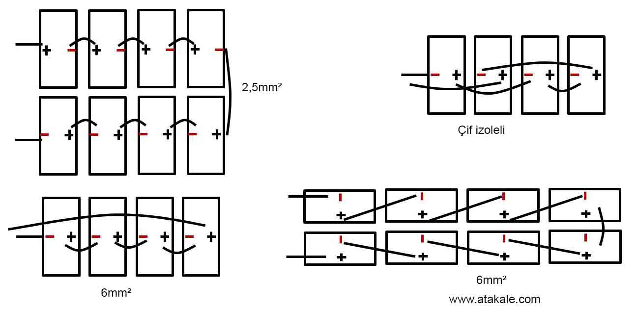
Çatı güneş Paeli solar panel kablo bağlantısı.
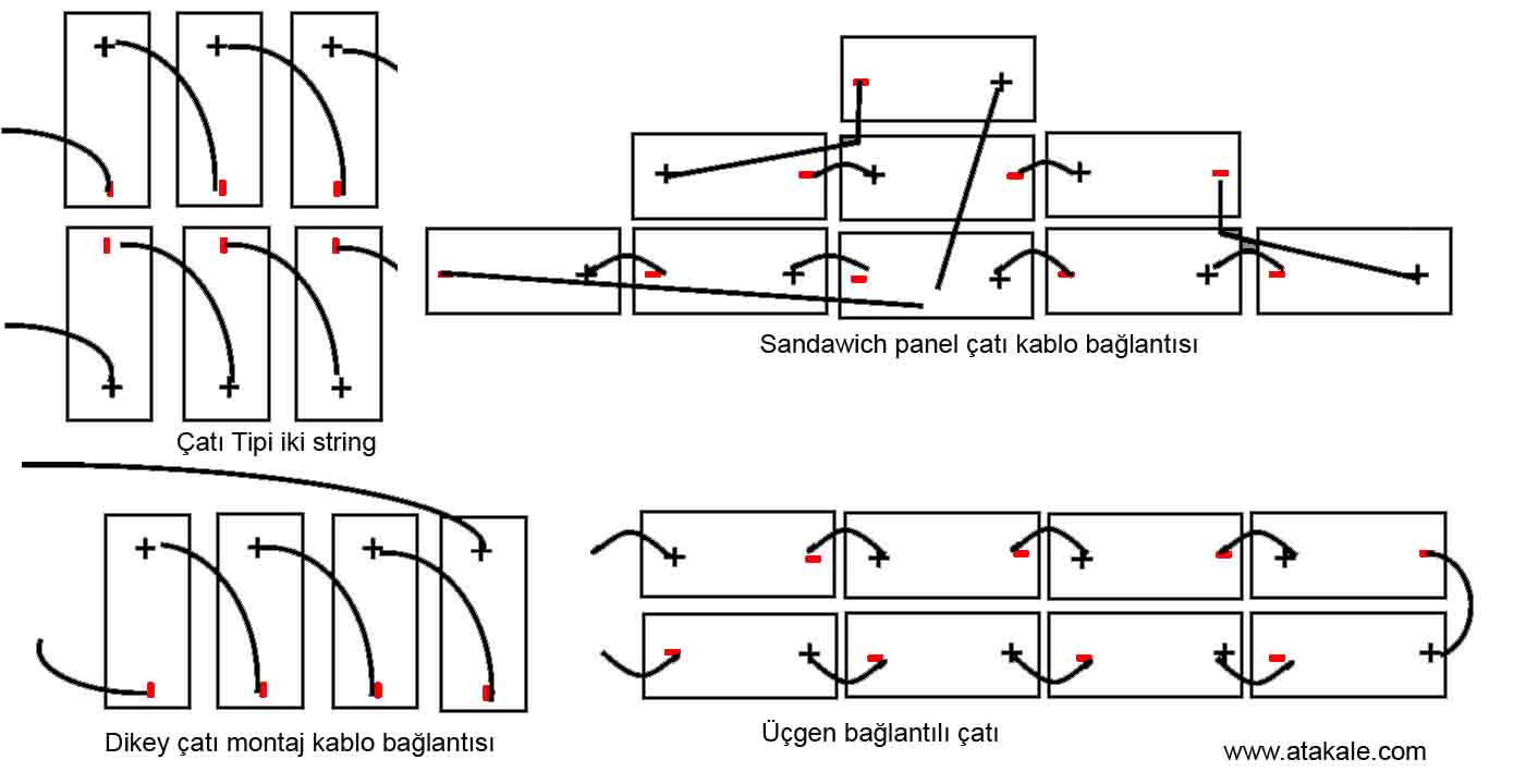
Solar Güneş Paneli Kablo Bağlantı Örnekleri.
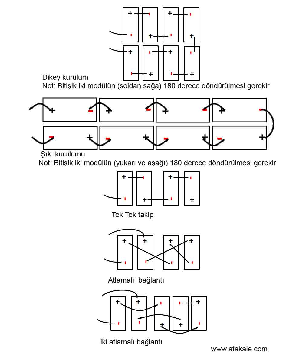
Sistem kablo şemasını karşılamak için iki bitişik modül çerçevesi arasındaki maksimum mesafe, montaj kelepçeleri olan taraf için 50 mm (1,96 inç) ve montaj kelepçeleri olmayan taraf için 25 mm (0,98 inç) içinde olmalıdır.
MC4 KONNEKTÖRLERİNİN DOĞRU BAĞLANTISI
◦ Tüm bağlantıların güvenli ve doğru şekilde eşleştirildiğinden emin olun. PV konektörü dışarıdan gelen çekemye maruz bırakılmamalıdır. Konektörler sadece devreyi bağlamak için kullanılmalıdır. Devreyi açıp kapatmak için asla kullanılmamalıdırlar.
◦ Konektörler, eşleştirilmediği zaman su geçirmez değildir. Modülleri takarken, konektörler mümkün olan en kısa sürede birbirine bağlanmalı veya konektöre nem ve toz girmesini önlemek için uygun önlemler alınmalıdır.
◦ Konektörleri yağlayıcılar veya izin verilmeyen herhangi bir kimyasal madde kullanarak temizlemeyin veya ön koşullandırma yapmayın.
UYGUN MALZEME KULLANIMI
◦ Yalnızca yerel yangın, bina ve elektrik yönetme liklerine uygun özel güneş enerjisi kablosu ve uygun konektörler kullanın (kablolar güneş ışığına dayanıklı bir kanalda veya maruz kalması durumunda güneş ışığına dayanıklı olmalıdır).
◦ Tesisatçılar, yalnızca USE-2 veya PV teli olarak listelenmiş ve etiketlenmiş tek iletkenli kablo kullanabilirler. Uluslararası 90°C suya dayanıklı olarak sınıflandırılmıştır ve tek iletkenli kablo, 2.5-16 mm² (5-14 AWG ), diğer alanlarda 90°C suya dayanıklı olarak sınıflandırılmıştır (yani TUV 2PfG1169 veya EN50618 onaylı), uygun izolasyona sahip, mümkün olan maksimum sistem açık devre voltajına dayanmalıdır.
◦ Sadece bakır iletken malzeme kullanıl malıdır. Voltaj düşüşünü en aza indirmek için uygun bir iletken ölçer seçin ve iletken akımının yerel düzenlemelere (yani NEC 690.8(D)) uygun olduğundan emin olun.
KABLO VE KONNEKTÖRLERİN KORUMASI
◦ UV ışınlarına dayanıklı kablo bağları kullanarak kabloları montaj sistemine sabitleyin. Uygun önlemleri alarak (örneğin, bunları EMT kanalı gibi metalik bir kanal içine yerleştirerek) açıkta kalan kabloları hasardan koruyun. Doğrudan güneş ışığına maruz kalmaktan kaçının. Bağlantı kutusu kablolarını raf sistemine sabitlerken minimum 60 mm (2,36 inç) bükülme yarıçapı gereklidir.
Konektörleri suyun kolayca birikebileceği yerlere yerleştirmeyin. Konnektörleri su birikecek yerlere koymayınız.
TOPRAKLAMA
• Standart opraklama yönetmen liğpi için, açıkta kalan iletken parçalara sahip bir modülün, yalnızca aşağıda verilen talimat lara ve Ulusallararası Elektrik Yönetmenliklere göre kurulması gerek lidir. Atakale . modülleri ile kullanılan herhangi bir topraklama aracı UL 467 ve UL 2703 standartlarına göre NRTL sertifikalı olmalıdır. Resmi onay süreci için lütfen teknik servis ekibimize danışınız.
• Diğer alanlardaki topraklama yönetme likleri için modüller Güvenlik Sınıfı II sertifikasına sahip olsa da, topraklanmalarını Stanartlara uygun yapılması gerekir
• Topraklama bağlantıları, bir kalifiye elektrikçiye yaptırmanız gerekir.
• Modül çerçevelerini yeterli topraklama kabloları kullanarak birbirine bağlayın: 4-14 mm² (AWG 6-12) bakır tel kullanılmasını öneririz. Bu amaç için sağlanan delikler, bir topraklama sembolü ile tanımlanır (IEC 61730-1). Tüm iletken bağlantı noktaları sıkıca sabitlenmelidir.
• Kolaylık sağlamak için fazladan toprakla ma deliği açmayın, bu modül garantisini geçersiz kılacaktır.
• Aksi belirtilmedikçe tüm cıvatalar, somunlar, düz rondelalar, kilit rondelaları ve diğer ilgili donanımlar paslanmaz çelikten yapılmalıdır.
• Atakale Solar topraklama donanımı sağlamaz. Topraklama ürünleri montajcı tarafından projeye uygun tedarik edilir
• Atakale Solar Inc. Standart modülleri için aşağıda açıklandığı gibi bir topraklama yöntemi önerilir. Alternatif topraklama yöntemleri için lütfen bu kurulum kılavuzunun Ek B'ye (Alternatif Topraklama Yöntemleri) bakın. Bazı durumlarda Standart topraklama yöntemlerini kullanmak mümkün olmayabilir.
Aşağıdaki resimde güneş panellerinin nasıl birbirine topraklama bağlantısının yapıldığını gösteriyoruz. Somun ve civata arasında kablo papucu sıkılır.

· Bir M5 (3/16") SS başlık cıvatası, bir M5 (3/16") SS düz pul, bir M5 (3/16") SS çanak pul ve bir M5 (3/16") içeren bir topraklama kiti SS somunu (dişli), çerçeve üzerinde var olan bir topraklama deliğine bakır topraklama teli takmak için kullanılır (aşağıdaki resme bakın).
· Teli düz rondela ile ters rondela arasına yerleştirin. Galvanik korozyonu önlemek için fincan pulunun içbükey tarafı yukarı gelecek şekilde çerçeve ile tel arasına yerleştirildiğinden emin olun. SS dişli somunu kullanarak cıvatayı iyice sıkın. Bunu yapmak için bir anahtar kullanılabilir. Sıkma torku 3-7 Nm'dir (2,2-5,2 ft-lbs)
6.0 MONTAJ TALİMATLARI
İş güvenliği, kazaların önlenmesi ve şantiye güvenliğinin sağlanması ile ilgili yürürlükteki yönetmeliklere uyulmalıdır. İşçiler ve üçüncü şahıs personel, düşme önleyici ekipman giymeli veya kurmalıdır. Herhangi bir üçüncü şahıs, yaralanmalara ve hasarlara karşı korunmalıdır.
Montaj tasarımı, kayıtlı bir profesyonel mühendis tarafından onaylanmalıdır. Montaj tasarımı ve prosedürleri, geçerli tüm yerel yasalara ve ilgili tüm makamların gereksinimlerine uygun olmalıdır.
• Modülün UL 1703 ve IEC 61215 ile uyumlu olduğu, yalnızca modül bu kurulum kılavuzunda yer alan montaj talimatlarında belirtilen şekilde monte edildiğinde kabul edilir.
• Çerçevesiz (laminat) herhangi bir modülün, modül bu Standart kapsamında modülle test edilmiş ve değerlendirilmiş bir donanımla veya kurulu modülün uyumlu olduğunu belgeleyen bir saha denetimiyle monte edilmedikçe UL 1703 gerekliliklerine uygun olduğu kabul edilmeyecektir.
• Atakale Solar güneş panelinin yanında montaj aparatı satmaz. Montaj ürünlerini ayrıca almalısınız
• Standart modüller, onaylanmış birkaç yöntemden biri kullanılarak bir destek yapısına monte edilebilir. Bu yöntemlerden biri aşağıda açıklanmıştır. Diğer montaj yöntemlerinin detayları ve Atakale Solar tarafından özel modül aralıkları için önerilen yöntemler için lütfen bu montaj kılavuzunun Ek A'sına (Alternatif Montaj Yöntemleri) bakınız.
• Diğer kurulum yöntemleri hakkında bilgi için lütfen yerel temsilcinizle iletişime geçin. Tanınan bir kurulum yönteminin kullanılmaması, Atakale Solar güneş panellerininin . garantisini geçersiz kılacaktır.
• Uygun korozyona dayanıklı sabitleme malzemeleri kullanın. Tüm montaj donanımı (cıvatalar, yaylı rondelalar, düz rondelalar, somunlar) sıcak daldırma galvanizli veya paslanmaz çelik olmalıdır.
• Kurulum için bir tork anahtarı kullanın.
• Ek delikler açmayın veya modül çerçevesini değiştirmeyin. Bunu yapmak garantiyi geçersiz kılacaktır.
• Standart modüller yatay veya dikey yönlerde kurulabilir. Daha fazla rehberlik için ayrıntılı talimatlara bakın. Lütfen yoğun kar yağışı olan (> 2400 Pa) alanlarda, en alt modül sırasına zarar veren kar yüklerini önlemek için ek destek çubuklarının kullanılması gibi ek karşı önlemlerin dikkate alınması gerektiğini unutmayın.
· Hem mekanik stabiliteyi hem de uzun vadeli modül performansını iyileştirmek